This page is a memorial to Terry's amateur radio efforts during his life.
Terry worked as an RF/microwave technician with W7ZOI (Wes Hayward) during
spectrum analyzer development efforts at Tektronix during the late 1970s.
Terry joined Wes and myself at TriQuint Semiconductor working on new product
development during the 1990s when our focus was on 1st gen WiFi, GPS and low
band cell phone RFICs. Terry made significant contributions toward development
of RFICs that our team designed for the 1st generation of digital cell phone technology.
Terry worked very closely at TQS with KK7B (Prof. Rick Campbell) on advanced
receiver RFIC design and development during the 2000s.
Terry built a lot of his own rigs through the 50s, 60s, 70s and in to the 1980's.
Terry then co-authored numerous QST and QEX articles with Wes Hayward, W7ZOI
in the decades following the 1970s.
Terry built a number of HF projects for the classic "Solid State Design for the
Radio Amateur" (ARRL 1976).
I was fortunate enough to inherit the rigs Terry built for SSD.
What is presented here are better photos of the rigs Terry built that were part of SSD.
Another agenda for this memorial page is for builders (the few who are left)
to be able to have a better look at Terry's SSD rigs vs the small and grainy
images within SSD.
There are many construction techniques that Terry used that I think are relevant
for many home brew builders, especially beginners.
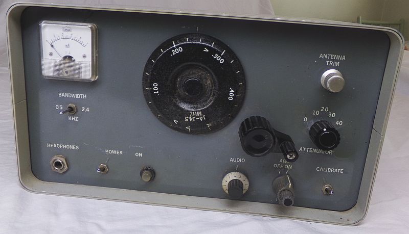
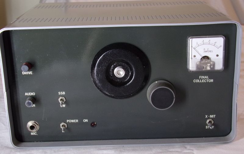
This is the 20m CW/SSB receiver from page xxx in SSD.
It is based on the then very coveted (expensive!) xtal filters from KVG.
Terry, like myself, appeciated the electrical and mechanical excellence
of the "Command Set" ARC-5 transmit and BC454 receiver geared air variable
capacitors. The worm drive mechanisms of the latter are superb for homebrew
applications.
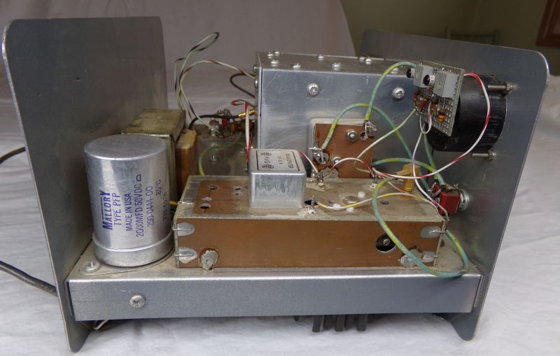
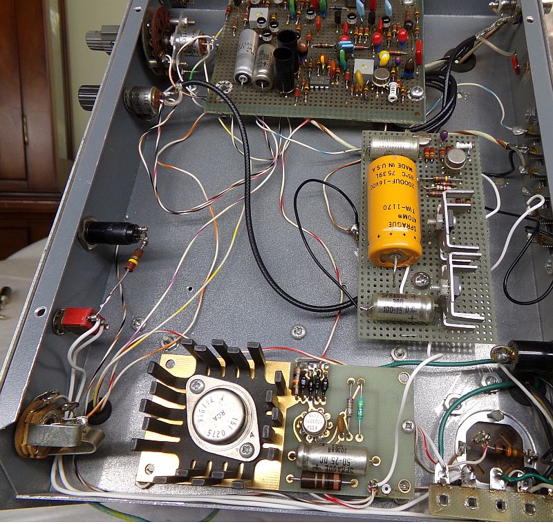
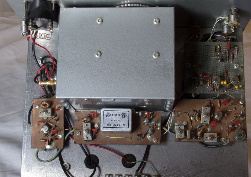
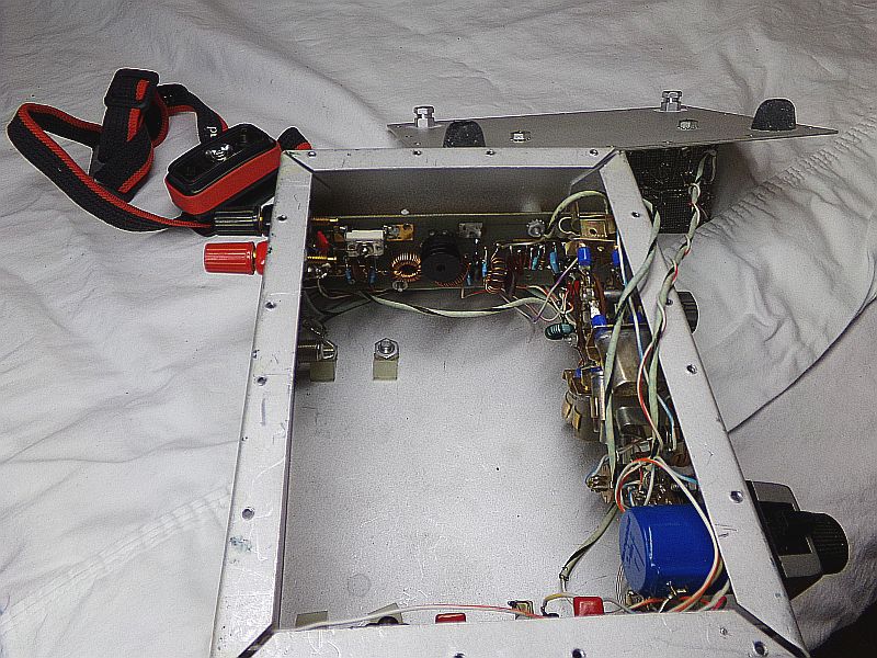
A side view of the 20m receiver.
IF gain stages are inside the Cu clad shielded enclosure.
Terry liked to include 120VAC power supplies in his larger chassis,
as can be seen by the line transformer and electrolytic cap along the
back wall of the receiver.
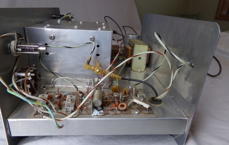
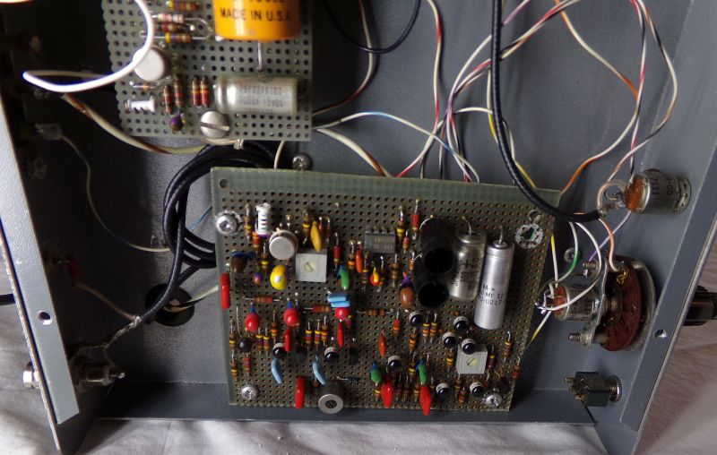
Front end band pass filter, LNA and image stripping filter on the left.
MC1496 product detector and 9 MHz BFO on the right.
Rotary switch on the front panel (left) is an RF input attenuator.
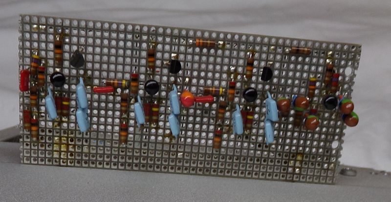
Note that this front end shows full "ugly" construction techniques, which
were a "new" approach compared to dedicated PCBs.
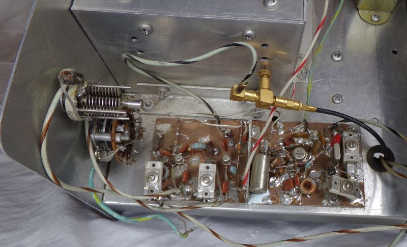
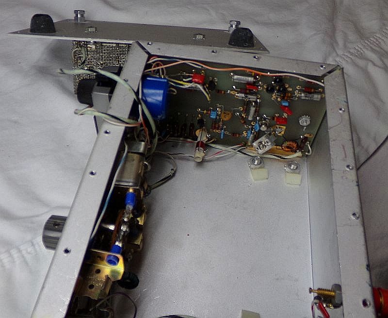
Top view of front end and product detector.
The front end is likely a 40673 dual gate MOSFET LNA followed by a 40673
mixer to down convert to the 9 MHz IF. This architecture was popular "back in
the day" as a way to implement band imaging for both transmit and receiver with
a 9 MHz IF such that a 5.0 MHz to 5.5 MHz VFO offered all of 80m & 20m coverage
with just selecting which front end band pass filter to use...3.5 MHz to 4 MHz,
or 14 MHz to 14.35 MHz.
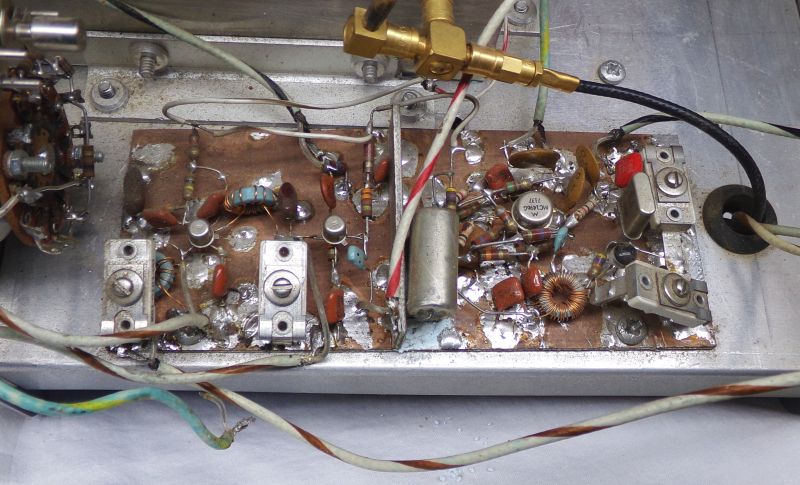
A closer look at the 20m front end.
Ugly method "Pros":
Cheap
Quick (10s of minutes per functional block...1 week via OSHPark).
Excellent circuit change flexibility
Mounting to chassis very easy.
Excellent performance for free running VFOs.
High quality (functional) labels can be done with white electrical tape and felt pen.
Felt pen labels can be moved if needed.
Ugly method "Cons":
Ugly (as if that matters)
No "professional looking" silk screen net and/or component labeling.
PCB "Pros":
Looks "professional" if done properly. (Irrelevant for home brew agenda)
Silk screen labels easily implemented.
PCB "Cons":
EXPENSIVE!
Long lead time (weeks back then).
Extremelty limited circuit change flexibility.
PCB is poor choice for free running VFOs.
Silk screen labels cannot be altered or moved AT ALL!.
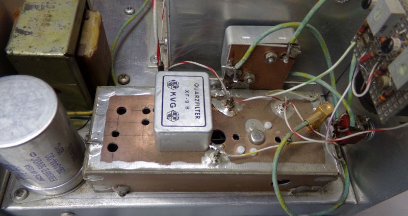
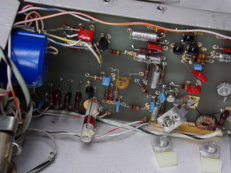
The XF-9-B is for SSB. The other module behind it has to be the XF-9-A for CW.
The can next to the XF-9-B is the front end post mixer broad band amp
at collector current of probably 50mA to 100mA.
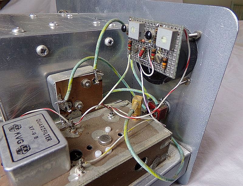
This has to be the audio chain and some IF AGC.

Top left is totem pole audio output stage for driving an 8 Ohm speaker direct.
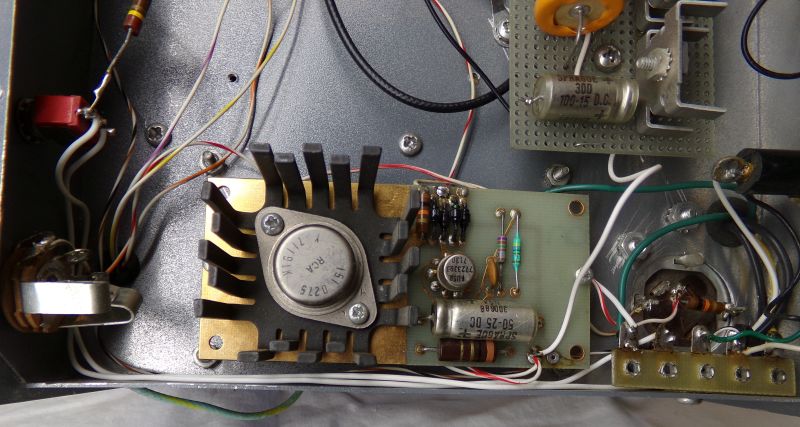
Lower board is a uA723 regualted power supply.
Terry seemed to really like these.
Lower board is a uA723 regualted power supply.
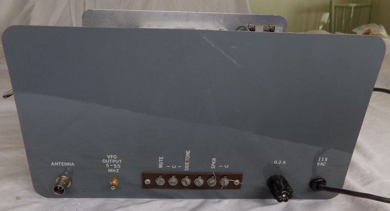
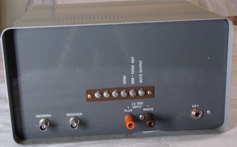
Back panel of the 20m receiver. Terry liked the press on labels.
that he would over spray with clear enamel to protect them from getting
scraped off later.
Front veiw of the 20m SSB transmitter.
Back panel veiw of the 20m SSB transmitter.
ARC-5 air variable VFO cap shielded in BUD chassis.
Upper right is mic audio gain.
Lower right is MC1496 DSB balanced modulator and 9 MHz carrier osc.
Lower middle is DSB broad band gain stage driving 9 MHz XF-9-A SSB xtal filter
followed by LC impedance match to the xtal filter output port.
Lower left is beginning of TX broad band gain chain.
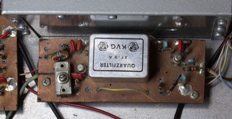
A closer view of the xtal filter circuitty.
Mic amp circuit. Not sure what the need for 2 op amps is.
One might be for just gain and the other for 3 kHz low pass?
Close view of DSB balanced modulator.
This is clearly a home etched PCB built prior to ugly adoption.

Broad band TX gain stages following xtal filter.
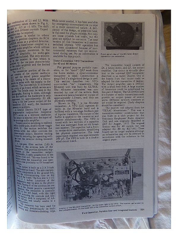
SSD page 221 photo of 80m CW txvr.
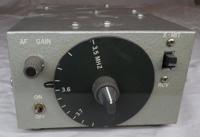
And here it is in real life...up close.
Terry used a vernier drive and added his own dial disc.
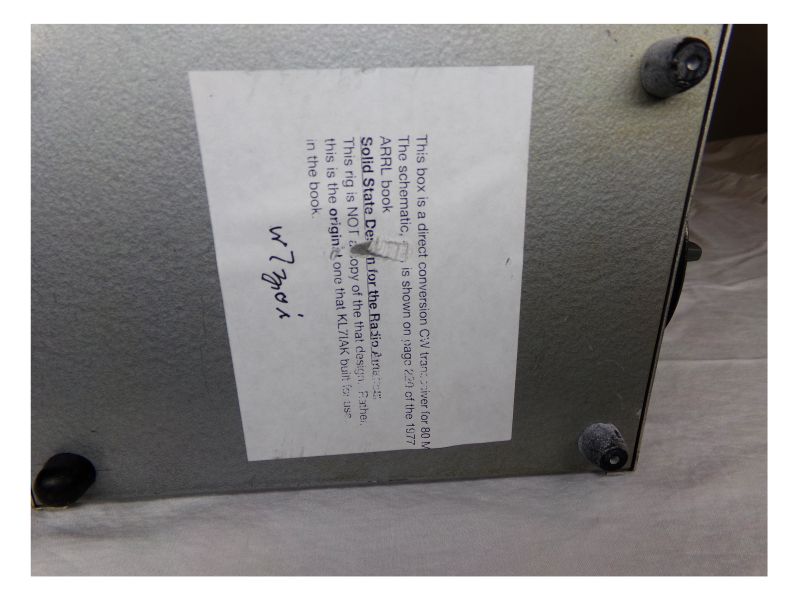
This is a note from W7ZOI about this version of the 80m CW txvr.
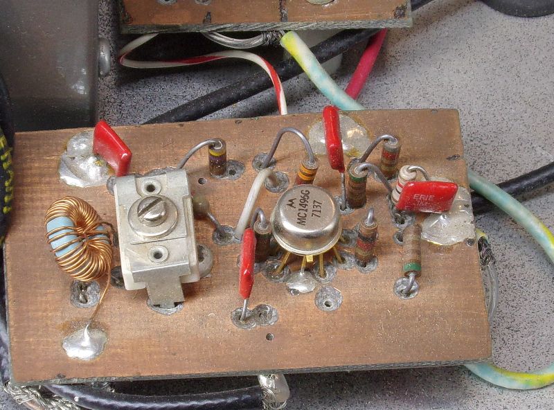
Receiver is direct conversion. The front board is most likely one of the
original "Mountaineer" boards that Wes and Terry fab'd in the Tektronix PCB
facility back in the day.
Top left is the VFO board. This was an era before we learned to not use silver
mica caps in free running oscillators, and to NOT use FR4 PCB material either.
Silver mica caps have a poor temp coefficient, and FR4 PCB dielectric constant
is also poorly behaved over temperature and humidity.
Top right board is PA output and TX LPF at around 1W to 1.5W out.

Another view of the same.

The PA section without much low pass filtering.
The latter not being very relevant at the 1W level, in practice and
with repsect to FCC Part 97.

Terry's xtal controlled 80m CW txvr.
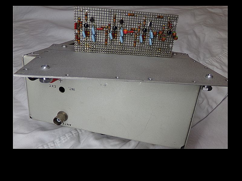
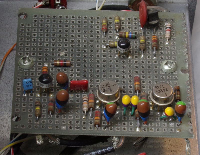
4 sections of active audio band pass filtering.
This was a big deal in those days.
A closer view of the audio band pass filter.
Discrete NPN transistors were used instead of op-amps.
The discrete approach is covered in detail in SSD.
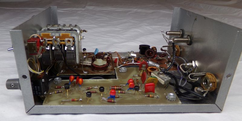
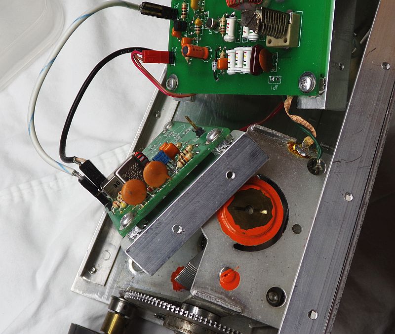
Interior view of the xtal controlled 80m CW txvr.
RX tuning is via VCO with 10 turn pot ( blue...lower right corner).

TX xtals are on a rotary switch in order to accomodate multiple frequencies.
Being "rock bound" back in those days was very common and not a detriment as
much as it is in the present era of 21st century.
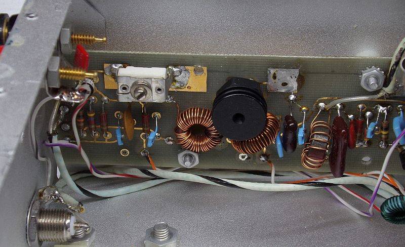
The receiver board is in the back. Most likely a "Mountaineer" receiver PCB.
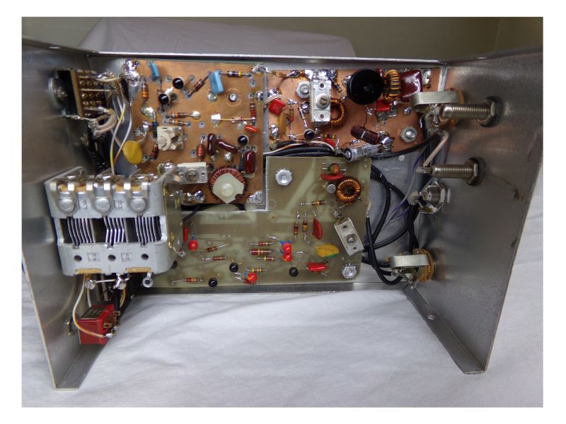
Sure looks like a Mountaineer board. 40673 dual gate MOSFET in lower right with
minimalist LC front end filtering. The cluster of 3 transistors is the side tone
audio oscillator and VSWR tuning "indicator", where the lower the tone, the lower
the TX VSWR.
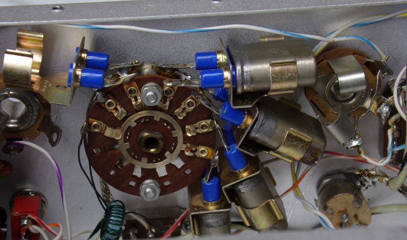
Close up of the TX xtals.
The TX output section.
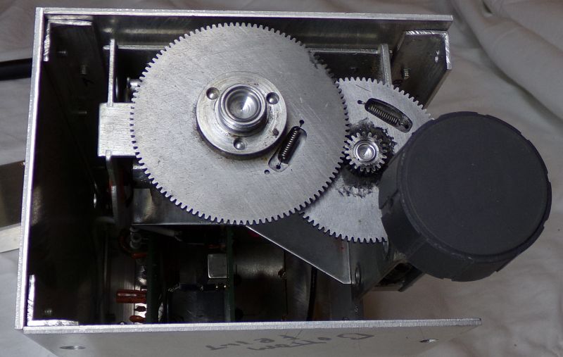
Terry did some truly beautiful machining on his VFO chassis.
This is an ARC-5 command set air variable as a 5MHz to 5.5 MHz VFO with
9 MHz xtal osc mixed up to 14 MHz.
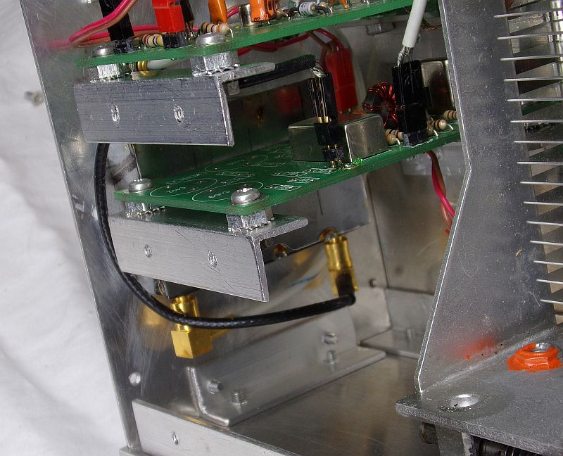
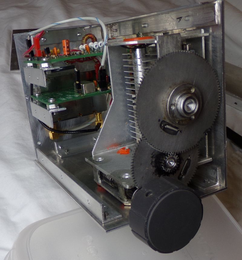
Another view of the ARC-5 5MHz to 5.5 MHz VFO up mix PCBs.
Terry and Wes made dedicated PCBs for this VFO up mix design.
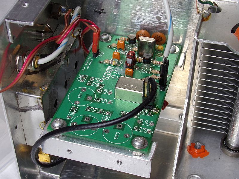
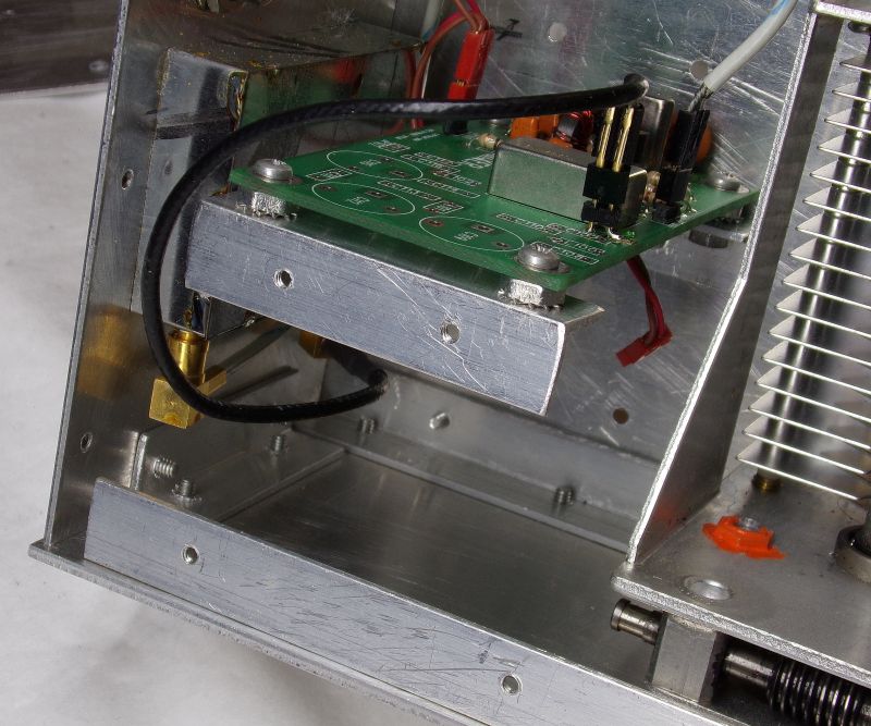
The up mix board.
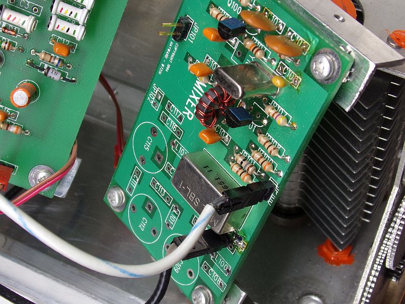
The up mix board.
The up mix board.
Why the VFO was done on FR4 is not clear.
K7TAU/KL7IAK (SK) History via W7ZOI
More WA7MLH
MC1496 product detector and 9 MHz BFO on the right.
Rotary switch on the front panel (left) is an RF input attenuator.
Note that this front end shows full "ugly" construction techniques, which
were a "new" approach compared to dedicated PCBs.
Top view of front end and product detector.
The front end is likely a 40673 dual gate MOSFET LNA followed by a 40673
mixer to down convert to the 9 MHz IF. This architecture was popular "back in
the day" as a way to implement band imaging for both transmit and receiver with
a 9 MHz IF such that a 5.0 MHz to 5.5 MHz VFO offered all of 80m & 20m coverage
with just selecting which front end band pass filter to use...3.5 MHz to 4 MHz,
or 14 MHz to 14.35 MHz.
A closer look at the 20m front end.
Ugly method "Pros":
Cheap
Quick (10s of minutes per functional block...1 week via OSHPark).
Excellent circuit change flexibility
Mounting to chassis very easy.
Excellent performance for free running VFOs.
High quality (functional) labels can be done with white electrical tape and felt pen.
Felt pen labels can be moved if needed.
Ugly method "Cons":
Ugly (as if that matters)
No "professional looking" silk screen net and/or component labeling.
PCB "Pros":
Looks "professional" if done properly. (Irrelevant for home brew agenda)
Silk screen labels easily implemented.
PCB "Cons":
EXPENSIVE!
Long lead time (weeks back then).
Extremelty limited circuit change flexibility.
PCB is poor choice for free running VFOs.
Silk screen labels cannot be altered or moved AT ALL!.
The XF-9-B is for SSB. The other module behind it has to be the XF-9-A for CW.
The can next to the XF-9-B is the front end post mixer broad band amp
at collector current of probably 50mA to 100mA.
This has to be the audio chain and some IF AGC.
Top left is totem pole audio output stage for driving an 8 Ohm speaker direct.
Lower board is a uA723 regualted power supply.
Terry seemed to really like these.
Lower board is a uA723 regualted power supply.
Back panel of the 20m receiver. Terry liked the press on labels.
that he would over spray with clear enamel to protect them from getting
scraped off later.
Front veiw of the 20m SSB transmitter.
Back panel veiw of the 20m SSB transmitter.
ARC-5 air variable VFO cap shielded in BUD chassis.
Upper right is mic audio gain.
Lower right is MC1496 DSB balanced modulator and 9 MHz carrier osc.
Lower middle is DSB broad band gain stage driving 9 MHz XF-9-A SSB xtal filter
followed by LC impedance match to the xtal filter output port.
Lower left is beginning of TX broad band gain chain.
A closer view of the xtal filter circuitty.
Mic amp circuit. Not sure what the need for 2 op amps is.
One might be for just gain and the other for 3 kHz low pass?
Close view of DSB balanced modulator.
This is clearly a home etched PCB built prior to ugly adoption.
Broad band TX gain stages following xtal filter.
SSD page 221 photo of 80m CW txvr.
And here it is in real life...up close.
Terry used a vernier drive and added his own dial disc.
This is a note from W7ZOI about this version of the 80m CW txvr.
Receiver is direct conversion. The front board is most likely one of the
original "Mountaineer" boards that Wes and Terry fab'd in the Tektronix PCB
facility back in the day.
Top left is the VFO board. This was an era before we learned to not use silver
mica caps in free running oscillators, and to NOT use FR4 PCB material either.
Silver mica caps have a poor temp coefficient, and FR4 PCB dielectric constant
is also poorly behaved over temperature and humidity.
Top right board is PA output and TX LPF at around 1W to 1.5W out.
Another view of the same.
The PA section without much low pass filtering.
The latter not being very relevant at the 1W level, in practice and
with repsect to FCC Part 97.
Terry's xtal controlled 80m CW txvr.
4 sections of active audio band pass filtering.
This was a big deal in those days.
A closer view of the audio band pass filter.
Discrete NPN transistors were used instead of op-amps.
The discrete approach is covered in detail in SSD.
Interior view of the xtal controlled 80m CW txvr.
RX tuning is via VCO with 10 turn pot ( blue...lower right corner).
TX xtals are on a rotary switch in order to accomodate multiple frequencies.
Being "rock bound" back in those days was very common and not a detriment as
much as it is in the present era of 21st century.
The receiver board is in the back. Most likely a "Mountaineer" receiver PCB.
Sure looks like a Mountaineer board. 40673 dual gate MOSFET in lower right with
minimalist LC front end filtering. The cluster of 3 transistors is the side tone
audio oscillator and VSWR tuning "indicator", where the lower the tone, the lower
the TX VSWR.
Close up of the TX xtals.
The TX output section.
Terry did some truly beautiful machining on his VFO chassis.
This is an ARC-5 command set air variable as a 5MHz to 5.5 MHz VFO with
9 MHz xtal osc mixed up to 14 MHz.
Another view of the ARC-5 5MHz to 5.5 MHz VFO up mix PCBs.
Terry and Wes made dedicated PCBs for this VFO up mix design.
The up mix board.
The up mix board.
The up mix board.
Why the VFO was done on FR4 is not clear.
K7TAU/KL7IAK (SK) History via W7ZOI
More WA7MLH
at collector current of probably 50mA to 100mA.
This has to be the audio chain and some IF AGC.
Top left is totem pole audio output stage for driving an 8 Ohm speaker direct.
Lower board is a uA723 regualted power supply.
Terry seemed to really like these.
Lower board is a uA723 regualted power supply.
Back panel of the 20m receiver. Terry liked the press on labels.
that he would over spray with clear enamel to protect them from getting
scraped off later.
Front veiw of the 20m SSB transmitter.
Back panel veiw of the 20m SSB transmitter.
ARC-5 air variable VFO cap shielded in BUD chassis.
Upper right is mic audio gain.
Lower right is MC1496 DSB balanced modulator and 9 MHz carrier osc.
Lower middle is DSB broad band gain stage driving 9 MHz XF-9-A SSB xtal filter
followed by LC impedance match to the xtal filter output port.
Lower left is beginning of TX broad band gain chain.
A closer view of the xtal filter circuitty.
Mic amp circuit. Not sure what the need for 2 op amps is.
One might be for just gain and the other for 3 kHz low pass?
Close view of DSB balanced modulator.
This is clearly a home etched PCB built prior to ugly adoption.
Broad band TX gain stages following xtal filter.
SSD page 221 photo of 80m CW txvr.
And here it is in real life...up close.
Terry used a vernier drive and added his own dial disc.
This is a note from W7ZOI about this version of the 80m CW txvr.
Receiver is direct conversion. The front board is most likely one of the
original "Mountaineer" boards that Wes and Terry fab'd in the Tektronix PCB
facility back in the day.
Top left is the VFO board. This was an era before we learned to not use silver
mica caps in free running oscillators, and to NOT use FR4 PCB material either.
Silver mica caps have a poor temp coefficient, and FR4 PCB dielectric constant
is also poorly behaved over temperature and humidity.
Top right board is PA output and TX LPF at around 1W to 1.5W out.
Another view of the same.
The PA section without much low pass filtering.
The latter not being very relevant at the 1W level, in practice and
with repsect to FCC Part 97.
Terry's xtal controlled 80m CW txvr.
4 sections of active audio band pass filtering.
This was a big deal in those days.
A closer view of the audio band pass filter.
Discrete NPN transistors were used instead of op-amps.
The discrete approach is covered in detail in SSD.
Interior view of the xtal controlled 80m CW txvr.
RX tuning is via VCO with 10 turn pot ( blue...lower right corner).
TX xtals are on a rotary switch in order to accomodate multiple frequencies.
Being "rock bound" back in those days was very common and not a detriment as
much as it is in the present era of 21st century.
The receiver board is in the back. Most likely a "Mountaineer" receiver PCB.
Sure looks like a Mountaineer board. 40673 dual gate MOSFET in lower right with
minimalist LC front end filtering. The cluster of 3 transistors is the side tone
audio oscillator and VSWR tuning "indicator", where the lower the tone, the lower
the TX VSWR.
Close up of the TX xtals.
The TX output section.
Terry did some truly beautiful machining on his VFO chassis.
This is an ARC-5 command set air variable as a 5MHz to 5.5 MHz VFO with
9 MHz xtal osc mixed up to 14 MHz.
Another view of the ARC-5 5MHz to 5.5 MHz VFO up mix PCBs.
Terry and Wes made dedicated PCBs for this VFO up mix design.
The up mix board.
The up mix board.
The up mix board.
Why the VFO was done on FR4 is not clear.