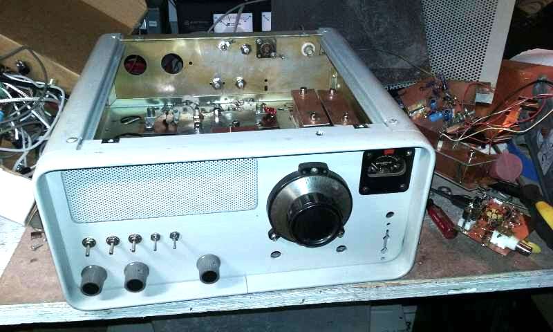
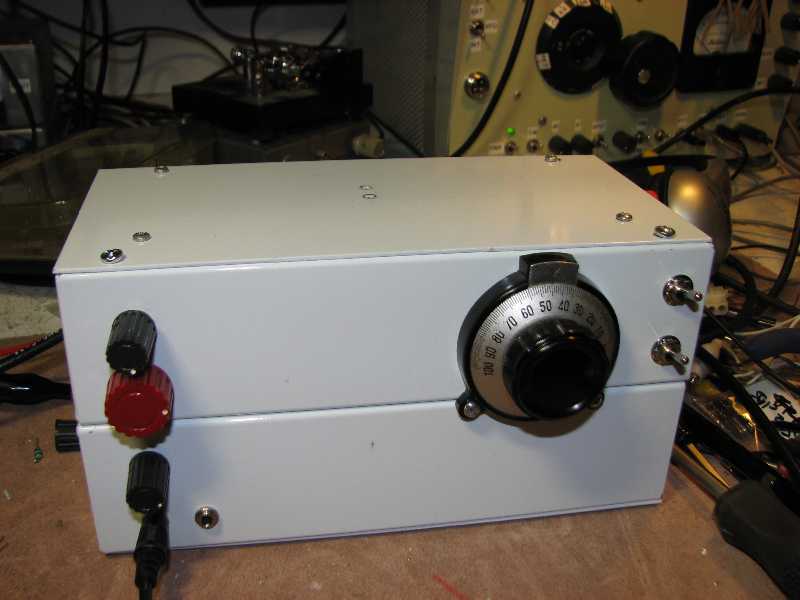
My first homebrew xtal filters in this 20m CW/SSB TXVR using 7.5 MHz IF.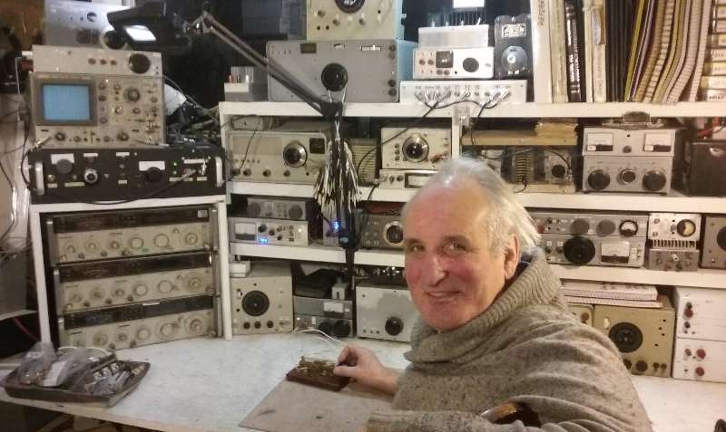
K7TAU/KL7IAK (SK 2023) Memorial Page
I got the xtals at the Rickreall Hamfest (OR) back in the late 1980s.
Filters are Cohn ladder topology (equal coupling coefficients with 5 xtals).
I am using them mainly due to the nostalgia of them being my first ever xtal filters.
Their performance is a bit lacking compared to proper Chebycheff design with more xtals.
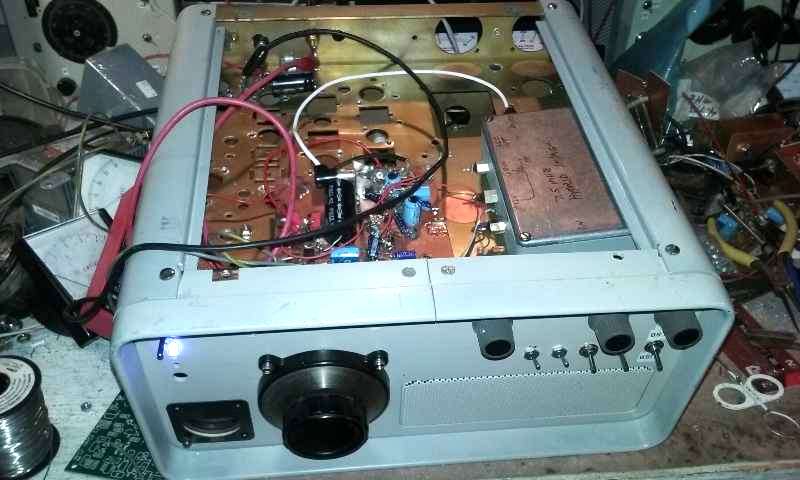
The chassis was a hamfest carcass with speaker grill and S meter already set up on the front.
It was years later I realized it was silly to worry about the cost of new xtals from Mouser/Digikey.
Buying 50 or 100 at about $0.32 each should never have been an issue since I would live with
and use the filters for the rest of my life. And I could build filters with performance far beyond
anything that was available as a commercial one, or one from a typical amateur "appliance".
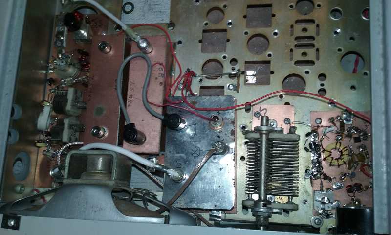
Hartley VFO at lower right at 6.5 MHz
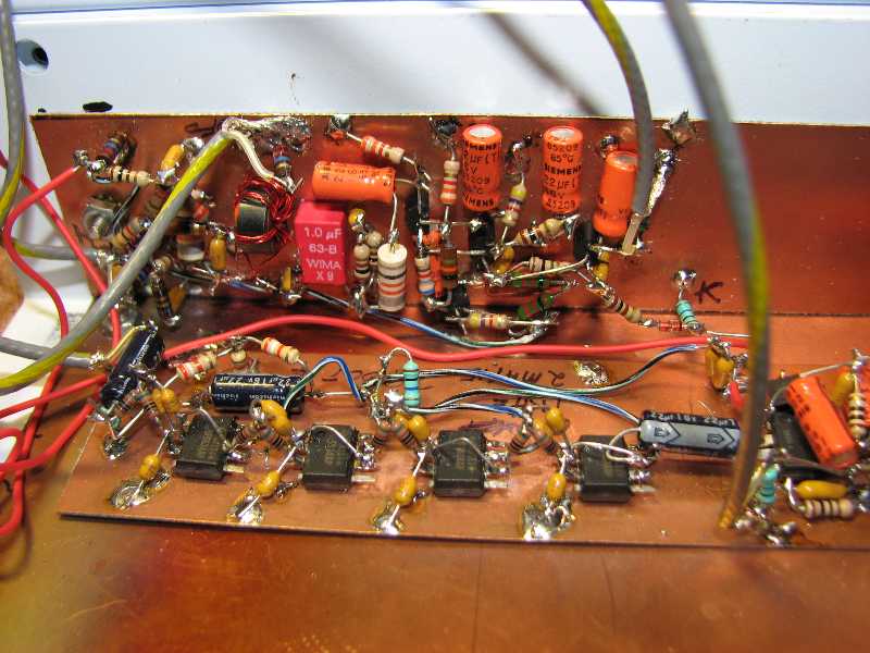
RX LNA is on far left, then xtal filters, then 1st IF RX diode ring mixer and post mixer broad band amp.
I chose phono connectors because they are cheap and easy to use while offering excellent performance up
through VHF
I confirmed the latter with an HP8753C vector network analyzer.
Turns out phono connectors perform really well out to 450 MHz!

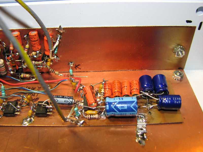
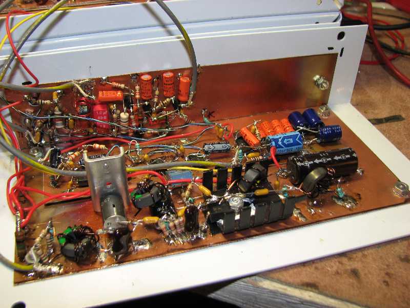
Hybrid cascode IF/AGC amp. Thank you KA7EXM for the PCB design!
IF/AGC amp on the right in a shielded Bud chassis.
RX audio section in the middle.
RX BFO. I like tuneable a BFO for RX over fixed xtal.
This is a VXO. The xtal is at the bottom of the photo.
I "pulled" the xtal frequency lower with about 5uH of series inductance so I could cover both sidebands.

7/7 TX & RX boards for QRP CW TXVR. These are for the W7ZOI design in EMRFD.
These were the first ones, so RX xtal filter is only 3 xtals.(As in original)
Next version added 2 more xtals so that the filter design would be easier in XLAD (from EMRFD).
XLAD08 has k&q bugs for 3 & 4 xtals with the default Gaussian to -6db response, requiring a manual
over-ride for k & q values.
I am not a proponent of board stuffing and then calling it home brew.
Stuffed PCBs are hard to debug and do not lend themselves to modifications the way ugly does.
Once an ugly version has been assembled and is up and running properly, then a PCB is fair game.
The one benefit of a PCB is that it can be replicated.
Not so much with the ugly method.
The upside of a PCB is that it offers a rigid formfactor that lets you know what chassis it will fit
in to before you start assembly.
Ugly method can actually take equal to or less time to assemble than board stuffing.
W7ZOI invested a fair bit of time in the design of the 7/7 system architecture to minimize RX
current drain (approx 30mA with headphones) while not significantly compromising RX dynamic range.
The 7/7 design can easily be set up for all bands from 160m trough 10m and would probably work well
on 6m.

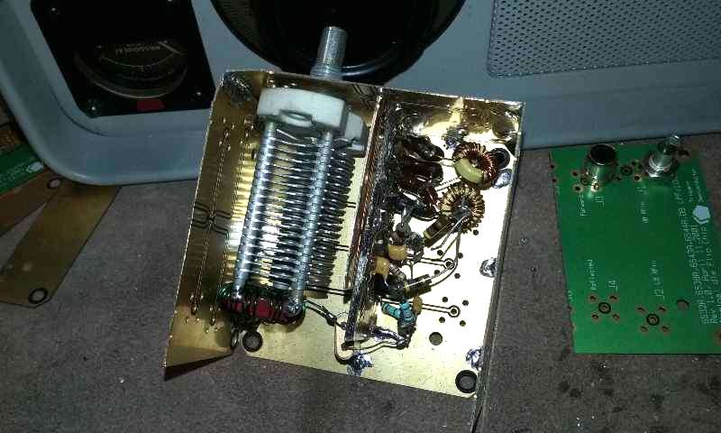
Took me decades to realize that a roller inductor in an antenna tuner has many drawbacks.
Qu of the roller inductor is easily degraded by poor contact mechanisms for the variable inductor "tap".
Most of the surplus rollers I have seen at hamfests and ones I have purchased had, in hind sight,
really bad electrical contact mechanics between the actual contact wheel and the wire on the solenoid.
Rollers tend to be large and heavy.
Clip leads on a solenoid inductor are easy to move and implement.
Plus, the plexiglass front panel allows me to see exactly where I am tapping.
Also, the AirDux does not need a turns counter!
And the AirDux and caps are quite cool looking IMHO.
#10 solid house wire wound on a cylindrical piece of wood or plastic would be a cheap and high Q inductor.
And the coil does not need to be cylindrical...a rectangular form will work just as well.
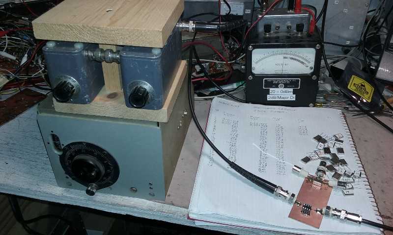
Unit on top is a 30W Wheatstone bridge for isolating the TX during tune up and measuring VSWR.
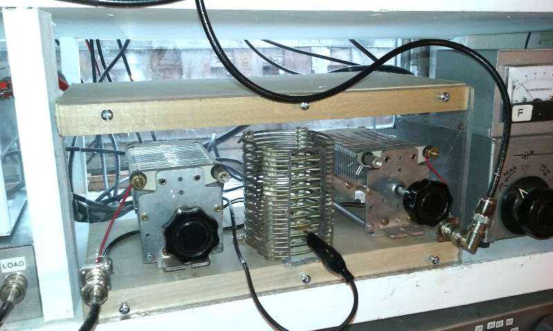
The CLC AirDux tuner ready for antenna matching. The wood base allows the caps to "float" in series.
Feb 2023: Another realization! The CLC topology has a problem. Both sides of the series tuning caps
at "hot", meaning that the rotor shafts are radiating in to the shack and cannot be "grounded" within
the network or a well shielded chassis. A proper implementation of the CLC matching network will
require the capacitor rotor shafts to be electrically isolated from a proper shielded chassis.
The plexiglass front and rear panels are a big no-no, as are the top and bottom wood panels!.
This unshielded format radiates in to the shack big time, which offers a huge stability problem while
working on TX chains open on the bench.
The magnetic field off of the inductor will couple in to the early stages of the power amp chain
and cause all sorts of instabilties that have nothing to do with the circuit design itself.
Very hard to debug!
This tuner approach needs some copper screen mesh wrapped around it as a Faraday cage.
Large mesh, like maybe 1/4" ought to work for VHF and below so that one can still see the caps settings.
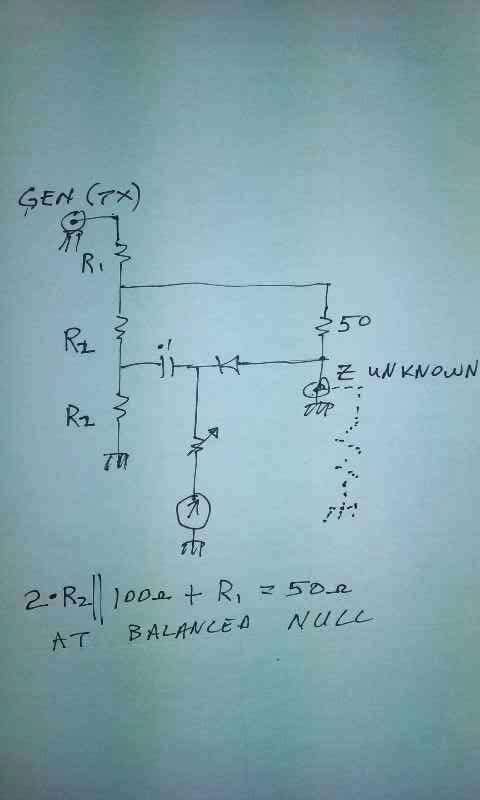
Wheatstone bridge schematic.
Lots of flexibility here in that one simply needs to get the ladders on each side set up as equal value resistors.
The left divider values do not have to equal the right divider.
Values are not critical. I paralleled up a bunch of 82 ohm 2W resistors I got at a hamfest for next to nothing.
The paralleled sets were then soldered together as series strings and measured with DMM to make sure they
were matched.
The nice feature of this bridge scheme is that under worst case loads of open or short, the TX nevers sees
worse than about 2:1 VSWR so it is always protected regardless of tuning. I use a DPDT switch to switch the
bridge in or out.
In hind sight, I think a directional coupler and high power dummy load is the better strategy.
WAY easier, and not much to fuss with to get it up and running. See EMRFD for details.
Thanks W7ZOI for this one!

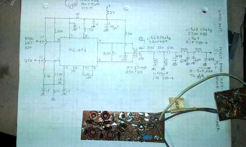
This is a rebuild of a 9 MHz IF HF CW/SSB TXVR I designed back in the late 1980s.
It uses a 1/1 analog PLL with 5-5.5 MHz master VFO and 12 slaved VCOs for high side LO injection
on both RX & TX paths.
Bummer is that 9 MHz sucks as an IF for the 17m band, so 17m will not happen in this one.
I had all of the RX path up and running when I accidentally had a power supply alligator clip
land on one of the KVG xtal filter pins! That fried the SSB filter.
It was a horrible sense of loss until, by sheer accident, I discovered that Mouser carries 9.000 MHz xtals!
That allowed me to keep all of the VCOs and xtal offset oscillators and build a very serious set
of filters that significantly outperformed the KVG filter by a lot!
Now this rig has 8 xtals at 3.2 KHz BW for SSB with approximately .1dB ripple Chebycheff response.
Good luck affording that kind of selectivity in a commercial filter, even if you could find it!
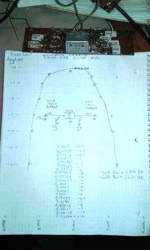
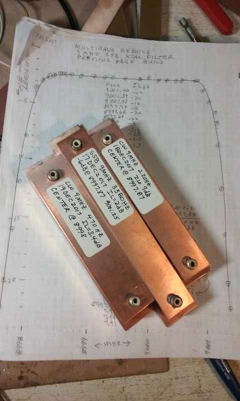
Now the rig has a pair of CW xtal filters of Gaussian to -6dB response for 220 Hz & 470 Hz BW.
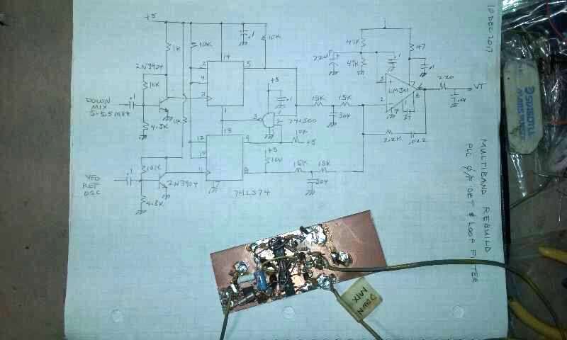
The ugly board is the PLL down mix with 5.5 MHz LPF and some gain before going in to the phase/freq det PCB
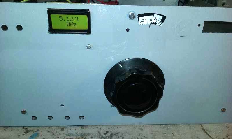
I opted for the convenience of using a cheap LCD freq counter to count the VCOs
and simply ignore the digits above the decimal.
The KVG SSB filter response before I zorched it.
I am not big fan of 2.6 KHz SSB filters because they lack the audio quality of a wider BW.
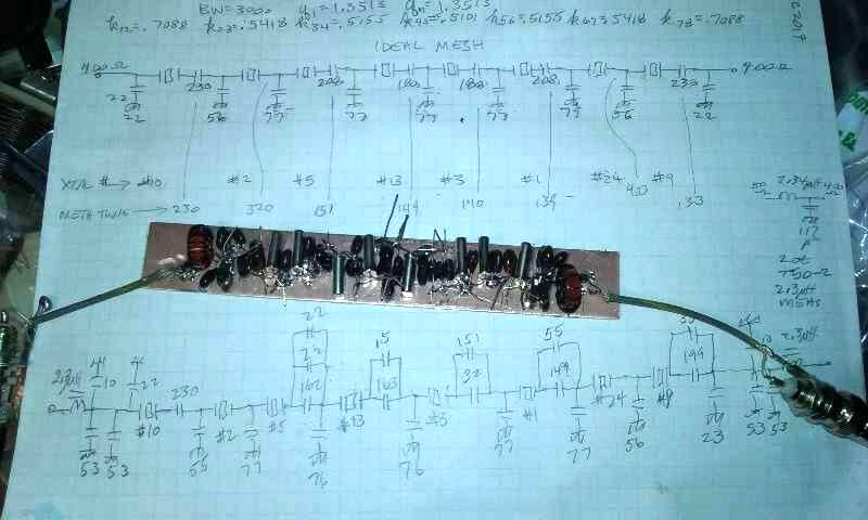
The new home brew SSB filter. This was mesh tuned in XLAD (EMRFD).
I used end section matching via LC networks because ALL of the filters I have built using
discrete transformers wound up with unpredictable "ears" on the skirts close in near the -6dB area.
I never use transformers on my xtal filters any more. Also, one can make the argument that
the extra L & C improve the skirt performance.(which they do, in theory)
9 MHz .1dB Chebycheff at approx 3.26 kHz. Design target was 3.0 kHz.
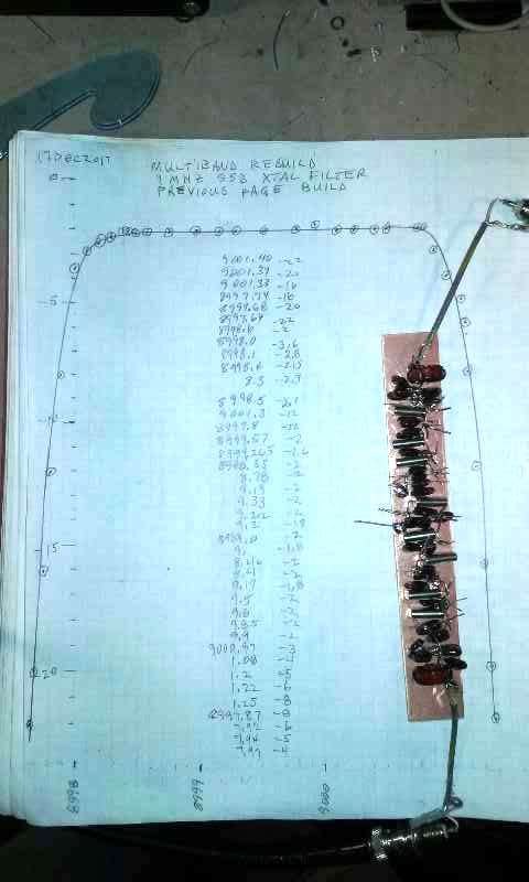
Amazing response for the new home brew SSB filter.
2dB insertion loss vs 6dB for the KVG!.
Not a big deal on TX but will help on improving system NF on RX.
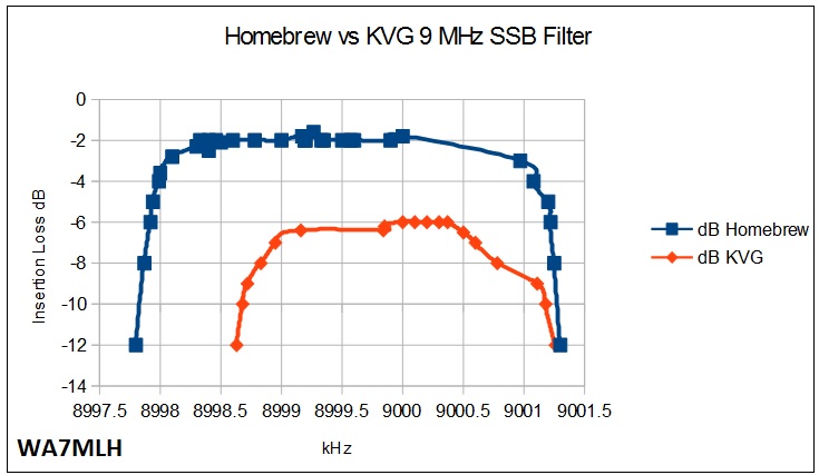
Comparison of insertion loss between KVG & homebrew xtal filter.
I need to get a few more data points to fill in the gap.
Then the KVG will look even uglier.
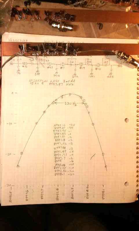
This CW filter came out to 220 Hz for Gaussian to -6dB response.
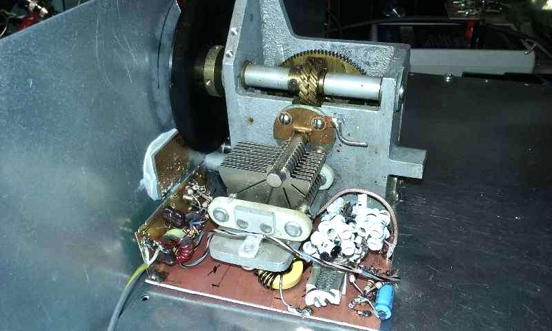
The Hartley VFO.
Lesson learned the hard way on this one...always build and test the VFO first before commiting to a chassis!
This air variable cap has a horrible temp coefficient and hence, the VFO has horrible drift.
Not sure how I will resolve this outside of brute force with N330 caps added in to the tank network.
I doubt I can replace the air variable itself. An external VFO will likely be a temporary fix.
RX tuneable BFO.
I have switched to RCA phono jacks for shielded interconnect in this rig.
They offer great RF performance in to UHF in spite of them being considered as audio connectors.
I learned that to my surprise by measuring them on an 8753B vector network analyzer.
And they are much cheaper than BNC and weigh less for protable rigs and take up less space than BNC.
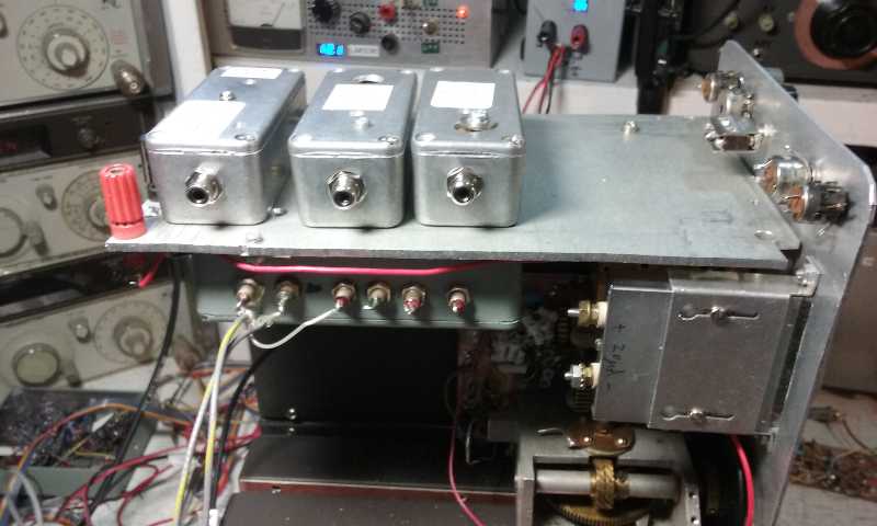
CW TX carrier xtal osc & LSB xtal BFO & USB xtal BFO.
Freq adjust happens through a hole in the lid for access to the tuning trimmer caps.
IF/AGC is in chassis under the plate.
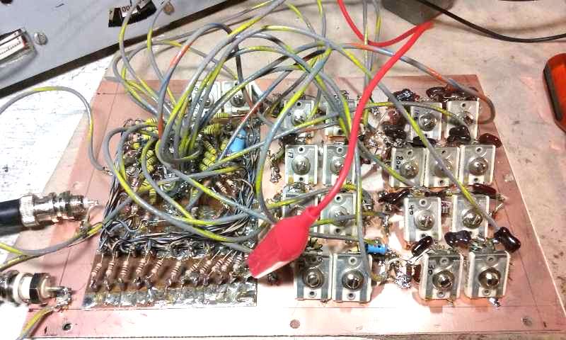
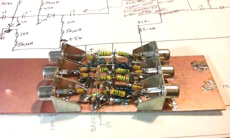
PIN diode switched DTC band pass filters for RX front end & TX mixed band select.
The PIN diodes (600V rectifiers) and support circuitry consume a huge amount of real estate.
I will likely opt for replacing all of these with SPDT pHEMT RF switches.
That will eliminate all of the inductors and current limiting resistors while offering
significant improvement in on/off isolation.
Also, in hindsight, even though the HV rectifiers are a true PNPN implant stack, the HV rectifiers
as RF PIN diodes have horrible off isolation compared to proper RF PIN diodes and pHEMT FET RF
switches, requiring extra shunt diodes and more current to get adequate port to port isolation.
The latter is not a problem for PIN switching xtal oscillators where only one oscillator is on
at any one time. The poor isolation is a major problem when switching a xtal filter or lumped LC
band pass filter between TX and RX paths in a transceiver.
Really bad system instabilities occured when I initially did not know to address the poor isolation
of just series HV rectifiers as the RF switches.
PIN diode DPDT switch for xtal filter path.
Diodes are 400V Si rectifiers at approx 30mA.
SPDT pHEMT switches are planned as replacements for these too.
The ugly version of the digital phase/freq detector.
MC1496 Gilbert/Jones cell balanced modulator.
Some readers might be interested in more of the history behind the 4 quadrant multiplier at
Analog RF History
The gain offered by the Jones-Gilbert Cell balanced modulator is easily replaced with a Schottky
diode ring and a single BB Amp gain stage. There is a lot of extranious RC parts needed to support
the MC1496. A diode ring will offer much better IMD performance than the MC1496 design.
With respect to RX dynamic range, the MC1496 and NE602/SA612 Gilbert cell mixers offer poor
performance as product detectors in single conversion receivers compared to diode rings.
The NE602/SA612 are reasonable choices for RX front ends in direct conversion and single conversion
receivers if high dynamic range is not a requirement.
My xtal characterization set up.
See EMRFD chapter (4?) on G3URR method.
Another good source for xtal characterization is the QEX paper by G3OTK at
An Automated Method for Measuring Quartz Crystals

Digital phase/frequency detector as a dedicated PCB.
I will probably use this one since it takes up less space than the original ugly version.
This is a shared (public) design at OSHPark
Since this circuit block more or less never changes and is not one that can be improved upon
via experimentation, it is therefore one that really supports the idea of a dedicated PCB.
Real estate can be reduced with SMD components, however, not by as much as one would think.
Turns out the solder pads for 0603 SMD components consume maybe 80% of the area required for 1/4W
axial leaded components. My experience is that for small PCBs for system block functions, the SMD route
does not offer much for PCB size reduction.
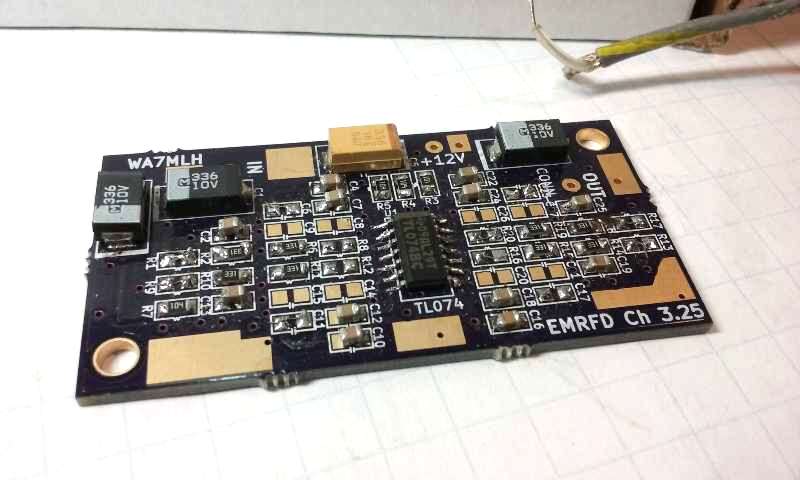
SMD 4 section Sallen-Key audio filter.
This was inspired by coming across about 100 cheap (free?) OP074 SOIC op amps.
This is a shared (public) design at OSHPark SMD Audio LPF
If you decide to build this make sure to keep your resistance values in k Ohms, not 100s of Ohms.
Many of the low power OP Amps cannot drive low impedances.
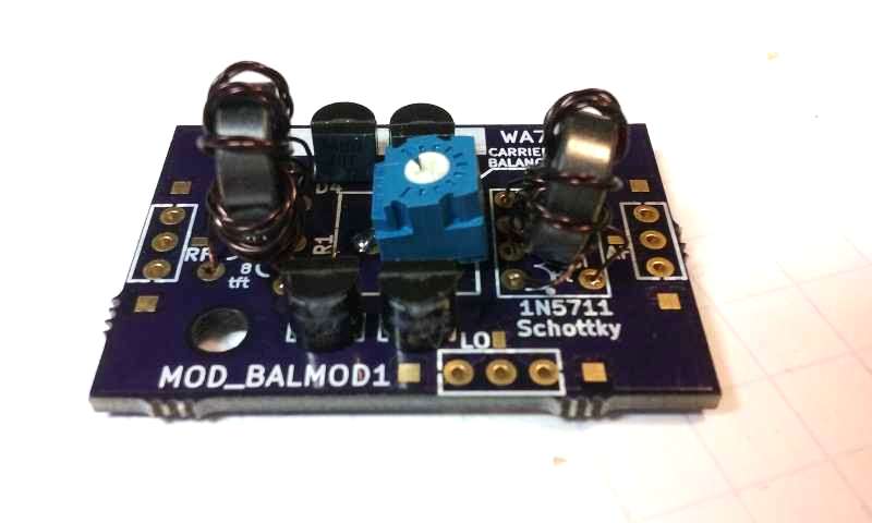
Diode ringe balanced modulator for generating DSB.
This is a shared (public) design at OSHPark MOD_BALMOD1
The pot is for carrier suppression, aka balance. Si Schottky diodes tend to be matched well enough that
they will perform well with no carrier balance adjustment for unwanted sideband suppression.
Generic juntion diodes will work fine as a balanced modulator when matched, although probably needing
closer to +10dBm LO drive vs +7dBm for Schottky diodes.
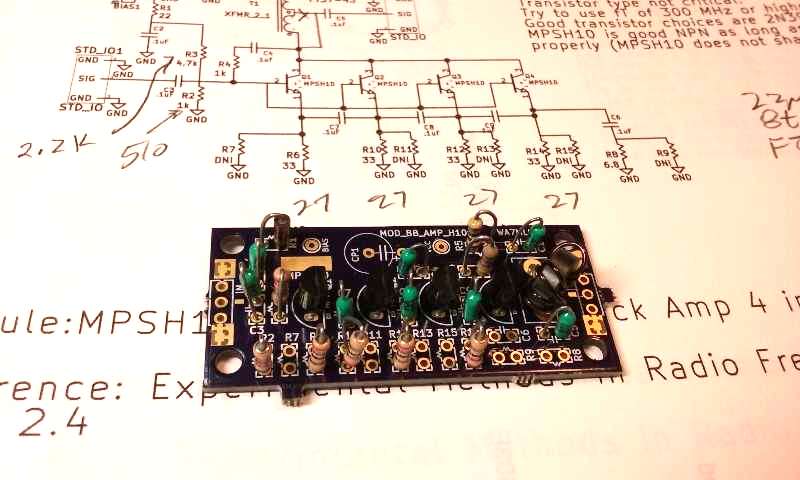
This is a nice compact broad band amp PCB designed around the TO-92 MPSH10 NPN.
MPSH10 has fT=650 MHz and is relatively cheap and easy to find.
With 350mW power dissipation and Ic=50mA (max) it is a great device for many HF applications.
Bias stabilization at DC is accomplished with emitter degeneration and AC coupled emitters
to parallel the devices at RF. This allows a lot of flexibility on the board for loading 1 to 4
transistors depending on how much power out one needs or an IMD agenda.
MPSH10s in this board work well out through 6m. Note that MPSH10 pin out is not the same as most NPN
in the TO-92 pkg.
4 devices at 250mW (DC) each will provide >+20dBm useful Pout for class AB SSB driver applications
or a superhet RX front end mixer post amp. The benefit of running at 250mW or less is not needing any
form of heat sink!.
Another option for this board is to bias for class AB, maybe 5mA per stage (min) and use it as a QRP final
at 1W out.
This design has a wide range of options for gain and power out depending on feedback and emitter resistor
values and bias setting on the base.
This is shared (public) at OSHPark BBAMPx4

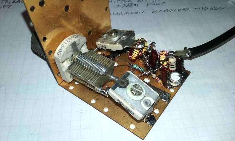
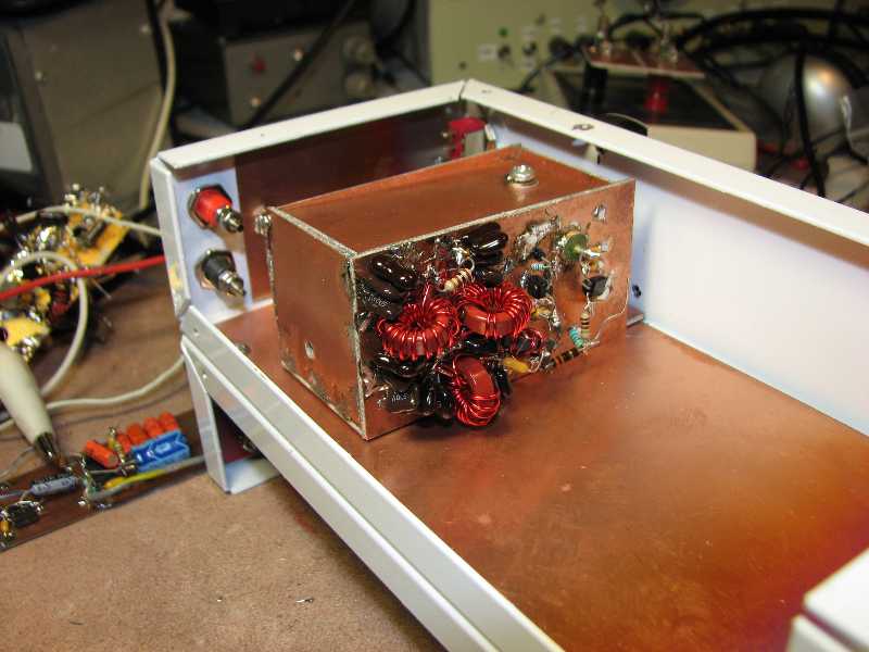
This is a 6 MHz SSB filter designed with 2 primary agendas.
One was to go through the "academic" exercise of extending the XLAD xtal filter software (EMRFD) out beyond its
default limit of 10 xtals. A bit of ASCII & notepad copy & paste allowed me to extend out to 14 xtals!!!
Two, these 6 MHz xtals I found for super cheap at SEAPAC hamfest (Oregon) turned out to have absolutely
stellar unloaded Qs, so they begged for becoming an amazing filter.
6 Mhz would not be my first choice for IF freq, yet it is quite OK for a lot of bands on TX,
especially with high side LO injection via 1/1 analog PLL.
This RX is now a working superhet on 75m with a 9.5-10 MHz Hartley VFO. I will rebuild with 1/1 loop
and add TX to it for a dedicated 80m/75m CW/SSB TXVR with low drift master VFO running 1.5-2 MHz
This xtal filter has since been updated to reside in a seriously shielded enclosure.
Lesson learned on this rig: All early TX path circuitry must be shielded!
This means shielding the TX up mix mixer, post mixer BBAMP and TX BPF so that a 100W PA signal
cannot "leak" back in to the TX signal path. Lack of TX path shielding caused really bad system instabilities.
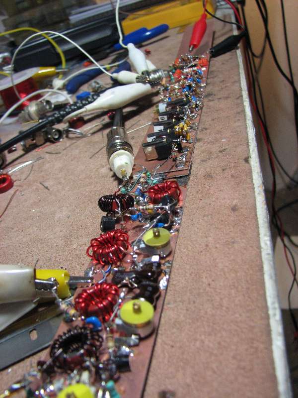
Ugly build up of 15m RX front end for a Field Day QRP CW TXVR.
I like to build up on the bench and verify everything is working before commiting to a chassis.
IF is 16 MHz (approx) with 5 xtals for Gaussian to -6dB response and 5 MHz VFO.
I found a lot of the 16.xxx MHz xtals at SEAPAC hamfest for super cheap.
They had the feature of being extremely tight on frequency, so I did not have to do any sorting.
Their Qu was not stellar, yet quite OK for a portable superhet RX.
80m Field Day CW TXVR. This uses a cascode of 2N4416 JFETs at around 3mA drain
current for the front end down convert mixer.
The 3mA is a compromise for lowered battery drain on RX vs dynamic range.
I have rarely (never?) found IMD to be a limiting issue in CW contests.
At least not in the 21st century.
The net effect of SKs, cell phones, the internet and no-code licenses has left the HF
bands very empty except for actual contests.

80m Field Day CW TXVR front end. A DTC BPF driving a cascode of 2N4416 JFETs

80m FDay Colpitts RX BFO tuneable from the front panel.
Series inductors with the xtal were needed to pull the osc freq lower than where it wanted to be.
Inductance value was empirically derived using what I could find in my junk box.
Due to the cost of molded axial lead inductors (new) I salvage inductors out of VHF/UHF
public service radio carcasses I get for cheap and hamefests
In hindsight, much larger Colpitts C values would have likely eliminated the need for the series inductance.
80m FDay active audio LPF. 4 sections of Sallen-Key low pass at 800 Hz
The audio low pass makes for a nice improvement over the wide band noise out of a typical
superhet audio chain.
80m FDay LM386 audio amp.
80m FDay TX chain for 5W variable Pout from an IRF-510.
Driver is 2N3866 as BB amp.

80m FDay TX chain PA LPF and RX LC tap off.
80m FDay VFO and external gain in to a Pi LPF.
Hartley VFO is inside the enclosure. Post osc gain is outside the enclosure to minimize drift
from the waste heat from the gain related transistors.


Salem OR Shack 2008
80m/40m Band Imaging RX
80m/40m Band Imaging RX2
80m/40m Band Imaging RX3
Rickreall Hamfest 2009
2nd Rickreall Hamfest 2009
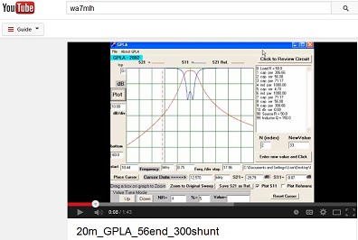
GPLA Double Tuned Circuit
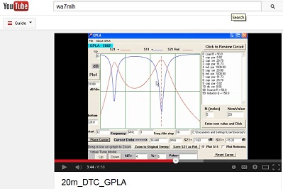
GPLA 20m Double Tuned Circuit Tutorial

Homebrew HF Power Amps
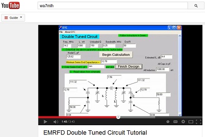
EMRFD DTC Filter Design Tutorial
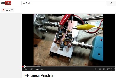
15W HF LDMOS Linear Amp

Updates: November 2009
Rickreall Feb 2009 Hamfest
Rickreall 2003 Hamfest
Rickreall October 2003 Hamfest
Rickreall October 2004 Hamfest
Rickreall February 2006 Hamfest
SEAPAC 2007 Hamfest
Rickreall October 2008 Hamfest
Rickreall October 2009 Hamfest